Prelude:
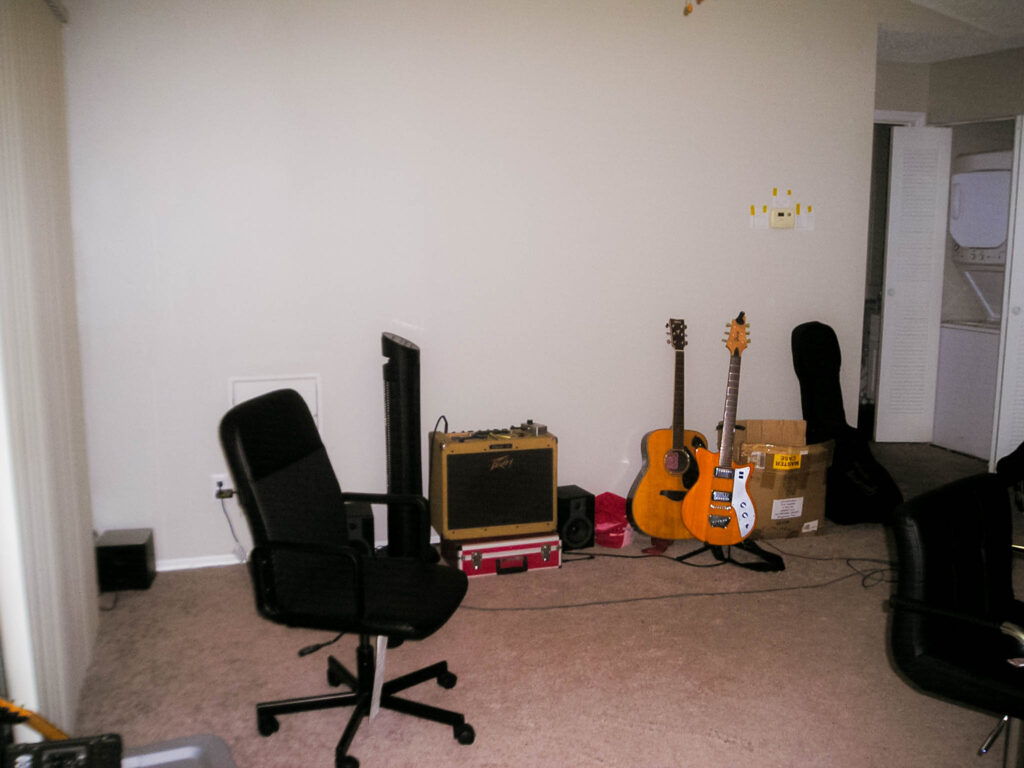
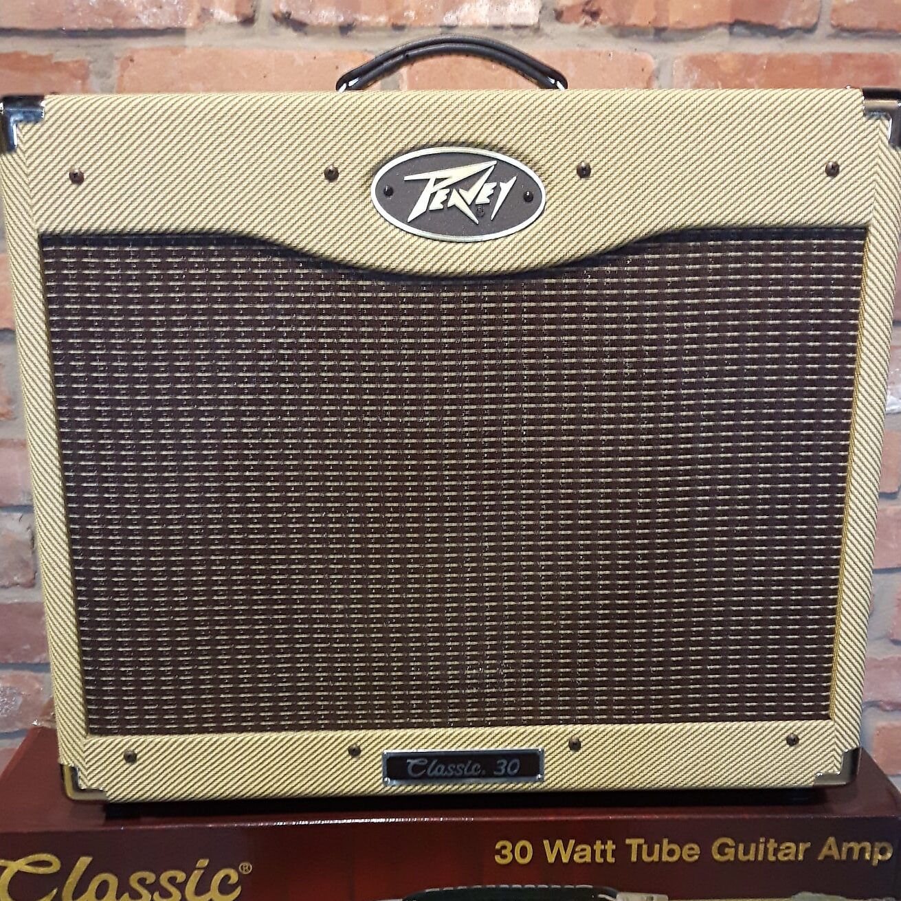
So I picked up a Peavey Classic 30 a few months ago for about $300 on FB marketplace. It was my first tube amp and even though I can’t crank it anywhere near the levels it should realistically be at, I’ve been quite happy with the amp and its sound. Tonally its pretty close to a Marshall type sound though not nearly as bright, and it has all the features you’d want out of “modern” tube amp (FX Loop, Channel Switching, Reverb, Master Volume etc.). Its also pretty loud for a 30 Watt amp and pretty damn heavy too. The only issues I personally have with it is mostly to do with the dirty channel. This is a pretty mid-heavy amp so you really need to turn down the mids on the EQ to avoid the amp sounding super boxy and unpleasant. The issue is the treble on the dirty channel is way higher than the clean, so if you want to switch channels with a footswitch you’ll be constantly fighting with the EQ since its so drastically different. This isn’t to say the dirty channel is bad, and I think pickups may have a lot to say in how hard it is to EQ between each channel (my pickups are quite bright even though they’re humbuckers). Regardless, there is a reason 90% of people who use this amp primarily just run the clean channel with some overdrive pedals in the front. This issue for me was compounded by the fact that, at the time, my only pedal was a Boss BD-2 which is notoriously bright even with the tone rolled back. This meant the thing was pretty harsh on the dirty channel but super nice on the clean channel, making EQ’ing between them even more difficult. To end this long ramble, the amp is cool and sounds great for such a cheap price, but there are some idiosyncrasies that can be frustrating depending on what you want out of the amp. Now to the problem:
The Problem:
So after a while this amp began to make a weird noise that sounded like it was almost choking. It also would experience occasional volume drops. I assumed this was the power tubes so I replaced all of them and the volume drops were somewhat dispelled but later on I started having weird noise issues with the amp that spawned this idea to open it up and start replacing stuff. If you want to know if I fixed this issue throughout this long journey servicing the amp, I suggest you skip to the last section as I have a lot to say about the common pitfalls of electronics, and in particular, tube amp repairs.
The Design:
This amp retailed back in 1993 for around $300 which was ludicrously cheap even for the time.
Due to this, Peavey had to make a lot of necessary concessions to cut prices so they wouldn’t lose money on each unit. This is where we get to the infamous 3-sided “circus boards” as D-Lab Electronics aptly refers to them. It isn’t an understatement to say that nearly every amp tech on the internet absolutely despises this thing and will nearly always refer to this amp as a piece of junk purely due to the poor needlessly complicated layout of this amp.

Before I get into the things that I think should be done when servicing this amp as well as the process, I want to defend Peavey’s design choices and put them into better context. Once again, this amp was very cheap for the time, so one of the big cost-cutting measures Peavey went for was trying to make this board as easy to mass manufacture as possible. This means no hand-wired turret-board circuits or point-to-point stuff, that costs a lot in labor. This is why most of these connections, sans a few which are hand soldered, are utilizing crimped connectors or soldered connections that can be easily assembled in a factory. We also have to remember this is the early 90’s, 2-4 layer boards weren’t as cheap as they are now and SMD components were no where near as cheap and widespread in consumer electronics back then (at least in the “dumber” consumer electronics). So utilizing a solution like this, with 3 single layer boards joined by cheap little jumpers to keep it compact and in place, may have been the cheapest and most ideal way for Peavey to produce an amp with this much power at such a price point.
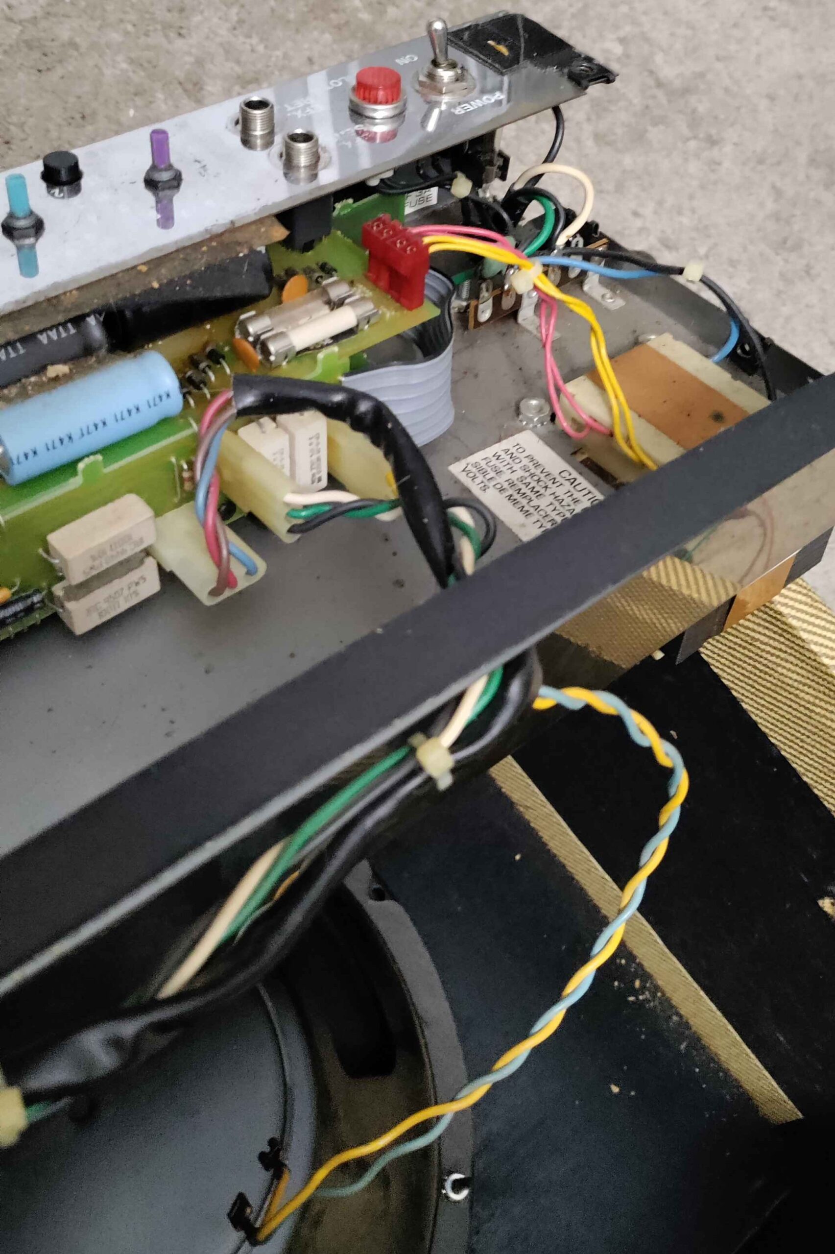
A lot went into the design of this board and you can even spot little choices that prove Peavey did attempt to make accommodations for people trying to open these up in the future. Probably the most interesting is the fact that nearly every connector except for two only goes in one way to prevent you from reversing anything and frying the board. Funnily enough, this board has no silkscreen at all, presumably to cut costs, so to signal the correct wiring of the connectors coming off the transformer’s secondary coil they drilled out the letters R and Y to show which color wire goes where. This works because adding some extra drill holes incurs no extra cost from the PCB manufacturer, but adding a whole silkscreen layer certainly would. Little things like this prove this amp’s design isn’t peculiar and frustrating due to ignorance or with the intent to dissuade third-party repairs/mods. The designers really did put work into figuring out how to make this thing as cost-effective and feature rich as possible with the limitations of the time.
Note: Okay so I’ve come back to this section of writing after some research and I guess some Classic 30’s did have silkscreen? This one I’m seeing off a telecaster forum shows white tube sockets and an actual silkscreen layer. So my points are still the same for the prior paragraph, but just keep in mind that apparently there are revisions that do have minute changes like this. This also kinda proves Peavey made a lot of “mini-revisions” leading up to the Classic II models that were just not explicitly documented. (Notice how they also have some different capacitor models and even 1% resistors as opposed to the 5% ones in my older model).

As much as people continue to hate on this design, the reality is most of these now 30 year old amps are still in working condition despite other design issues which I will get into in just a moment. Peavey’s are widely known as super reliable amps and hey if you bought one of these back in the day It likely would have lasted a while before common issues would begin to crop up. I would say 25+ years is a perfectly acceptable shelf life for a $300 amp.
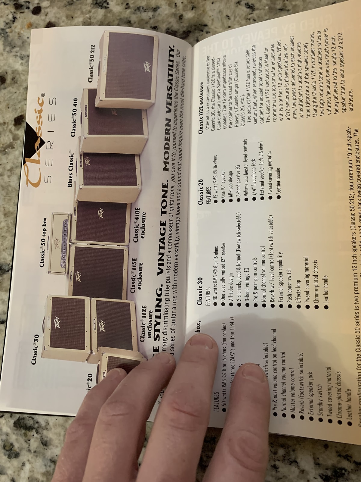
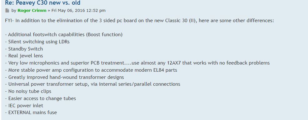
Another thing to note is that there were changes to this original design in later years that you may want to look at as opposed to buying these older models. The Peavey Classic II (the one where they put in that stupid badge so you couldn’t pretend it was a fender amp but then people got mad and they changed it back) fixes a lot of the design issues of the original with the caveat of having a higher cost on the used market. It is important to note I have seen these things go for only $100-$200 more than the OG Classic, so if you find a decent deal on these I would say its a much better investment than getting the original, especially if you don’t have the skills to service them. All of the 90’s Classic series original amps (Delta Blues, Classic 50, etc.) suffer from the same convoluted PCB design, but the newer models have replaced it with a more streamlined and repairable modern board design. There’s also been a lot of nice housekeeping changes that make the newer ones much more reliable and user friendly. A Peavey service manager describes the changes in a Peavey forum post here:
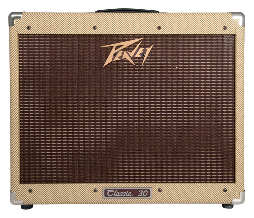
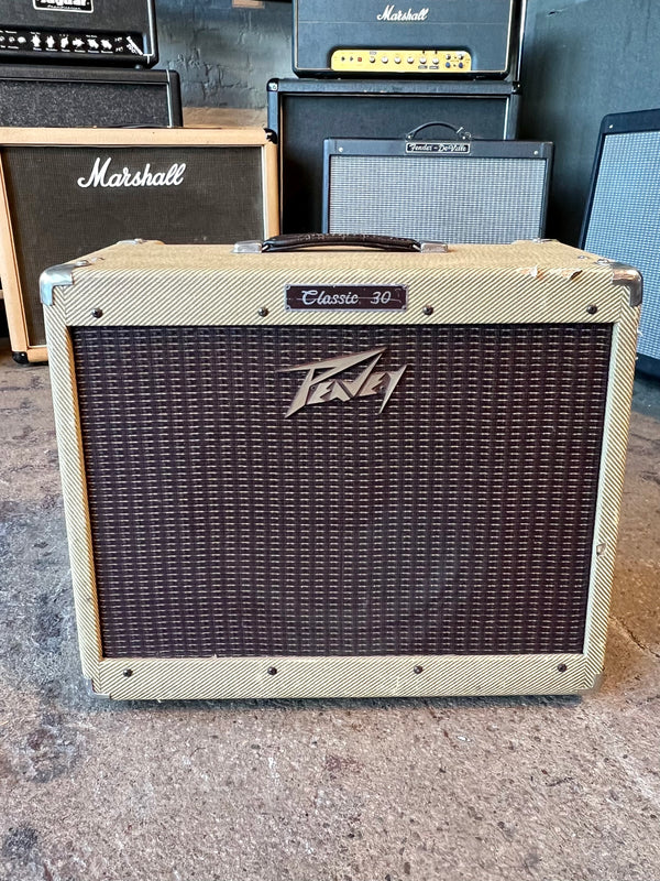
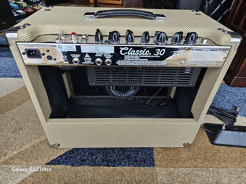
The main way to tell the difference between each model in the wild is the “Classic” silver badge on the top which is present in all older models; the newest ones have the badge at the bottom. If you aren’t already confused there are some OG Classic 30’s with the stupid badge in the middle just to make our lives as gear nerds even more complicated. The best way to tell the difference between the OG and the Classic II is to have a look at the back. There should be two switches: a power and standby switch. They also added a little cage around the tubes as opposed to the flimsy holders they had in the original model.
The final big change is they have nice AC socket adapter on the back instead of having the cable physically attached to the board, however, I believe some Classic II’s don’t have this change but someone can correct me if I’m wrong. All of these changes are big steps in the right direction for reliability, but lets face it, the OG models were produced in much greater numbers for a much longer time. I have seen some Classic II’s in the wild but 9 times out of 10 the only Classic models you’re gonna stumble upon for a cheap price is going to be one of the originals.
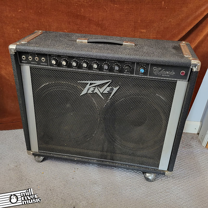
Some may have also realized I’ve neglected to mention the actual original Peavey Classics from the 70’s (VT series) which were hybrid amps with a solid state preamp and a tube power amp, which is a pretty unique and weird design. They also had a newer version called the Classic VTX in the 80’s which added some phaser effects because I guess that was all the rage back then. Are you confused yet? These amps seem to be pretty cool but the info on them is relatively slim since Peavey wasn’t as well know before the 5150 and Classic 30 craze in the 90s. They can be had for extremely cheap, and honestly a lot of these cheap Peavey solid state amps from the 70s/80s are genuine hidden gems so I would recommend picking one up if you’re interested and find a good deal. They also come in 2×12 arrangements just like some of the 90s Classic 30s which is pretty cool.
Issues:
The Capacitors:
The common go-to components to replace when servicing pretty much any old amp is the electrolytic capacitors. Specifically, the high-voltage capacitors that help filter out the power supply on the secondary of the transformer that feeds the power tubes. Most people don’t really care about the smaller low-voltage electrolytics which are purely there for tonal filtering and some necessary coupling here and there. Peavey opted to use Illinois Capacitors which depending on who you ask was a decent brand or relatively poor brand for electrolytics back in the 90s. I guess they aren’t Nichicons/Rubycons but honestly I think these things have gotten a slightly unfair reputation in these amps. I’ll get to this later when we start talking about the repair process, but I replaced every single one of these in my 1995 Classic 30 and only one of them was even remotely sketchy (ESR read 5ohms and it was a little low on capacitance). Everything else was perfectly in spec despite the amp being 30 years old. Now, to be fair there were a lot of Classic 30s made up until the newer designs started coming out, and we have to remember the capacitor plague in the late 90’s and early 2000’s was right in the middle of this manufacturing period. So where am I getting at with this? Well these capacitors aren’t necessarily ticking time bombs in my opinion, but if your amp was made in that late 90’s to early 2000’s period I would highly recommend a recap even if you think the amp isn’t necessarily old enough for a full service. Obviously if you plan to do anything but bedroom playing you probably want this thing serviced before going out on the road and having it crap out on you at some point.
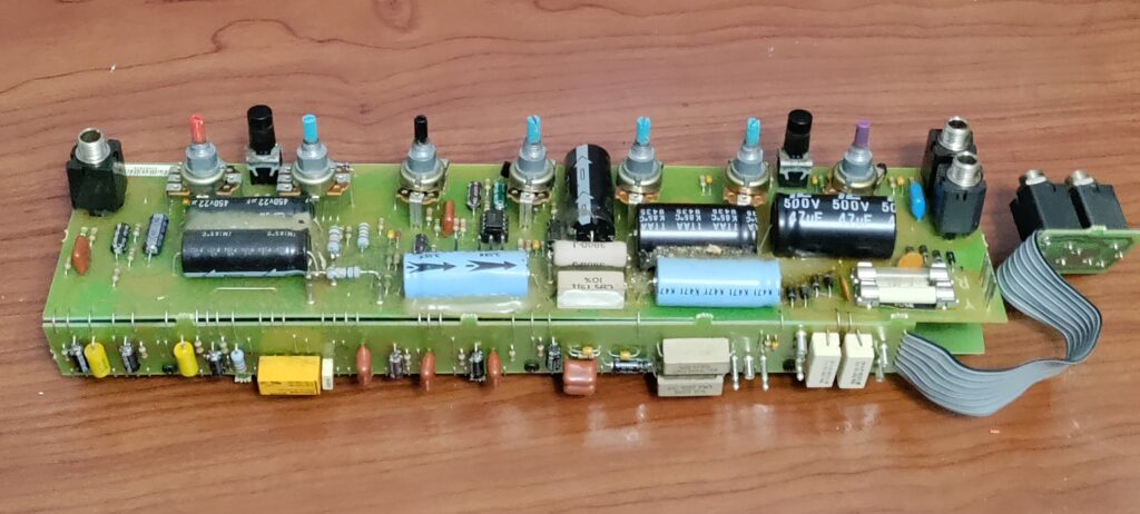
The main capacitors you want to replace on this thing are the 3 22uF 450V caps and the 2 47uF 500V caps on the top board with the potentiometers and Input/FX Loop jacks. I would also highly recommend replacing the 2 2200uF 50V caps even though they are “low voltage”. These are still necessary filtering caps that are directly on the secondary of one of the transformers, you want these to be in the best shape possible and they can definitely still fail. You want to replace all these caps with high quality replacements, I used F&T capacitors for the high voltage stuff since they were cheap, came in axial packages (this saves a lot of headache which you will see later), and they could be shipped to me quickly. There aren’t a lot of 500V axial electrolytics out there so I don’t mind promoting these. For the 2200uF caps I used some Panasonic radial caps I got off Tayda since I was already ordering stuff on there. Don’t be alarmed by these caps coming from Tayda they are not those cheapo JB electronics caps (no issue with these just wouldn’t use them for power filtering). Panasonics are one of the best name brand caps you can get so if you want replacement caps from Tayda as opposed to Digikey or Mouser I would say these are the best option. There’s also Nichicons/Rubycons/KEMET caps available on those other sites which are just as good. Unfortunately, the only axial 50V 2200uF caps I could find where also IC capacitors, so I guess you could just buy one from them but they are much pricier than their radial contemporaries. You may wonder if its even possible to use a radial cap as a replacement giver how large the pitch of the original axial caps are, but there is a workaround which we will discuss later.
The Screen/Grid Resistors:
This is a core design flaw with the Peavey Classic 30 OG models and before you say it no it was not intentional nor was it a tonal choice. Without getting too deep into it, with most tube amplifiers each tube will have a resistor tied to each tube’s screen with one node that goes to a high voltage screen supply. We could easily spend 50 pages talking about screen resistors and honestly I can’t say I completely understand them so take my 3 sentence amateurish explanation with a grain of salt. Essentially, these screen resistors are helpful for dropping some of the excess current that surges when you start turning the amp up and the plate voltages start rising. Its essentially there to make sure your tubes don’t burn up and to my knowledge allows them to last a bit longer. Keep in mind the Classic 30 is a notoriously hot circuit so this thing already has a reputation as a ‘tube eater’. The Classic 30 circuit, for some unknown reason, only has 2 100ohm screen resistors on only two of the power tubes. The other tubes are shorted together to the screen supply. There is debate on whether this was a cost-cutting measure or not as shown in this thread with a former Peavey designer from the time the Classic 30’s were being drafted: https://groupdiy.com/threads/peavey-tube-amp-output-tx-unbalanced-currents-missing-screen-resistors.64636/.
Technically, having a lower screen resistance allows you to squeeze more power out of your tubes and many designers back in the day took advantage of this, but I doubt this was the designers full intent especially since the circuit was already pushing the limits quite a bit already. Maybe we will never know, but we do know that Peavey later fixed this in the Classic II models and pretty much all of their later tube amp designs all had appropriate screen grid resistors on each power tube. EL84’s are recommended to have screen resistors with a value of 470-2k ohms or so on each tube. For our case we’ll choose the most common recommended value which seems to be about 1kohm. This screen grid resistor fix is what I would consider a bit of a necessity if you’re going to open this thing up at all, and thankfully these resistors aren’t very expensive either. Remember these resistors must be rated for at least 5W, I’ve seen some people get away with 3W but I personally wouldn’t chance it. If you’re wondering where I got my resistors from, I sourced all of them from my local electronics shop for about 50c each, but these can easily be sourced from Mouser/Digikey/Tayda. Make sure you’re buying wirewound resistors, the originals have a cemented enclosure but some of the stuff you can find online have different more rounded enclosures. This has no effect on anything, but if you want a more compact solution the rounder ones will be the ones to look out for.
Plan of Action:
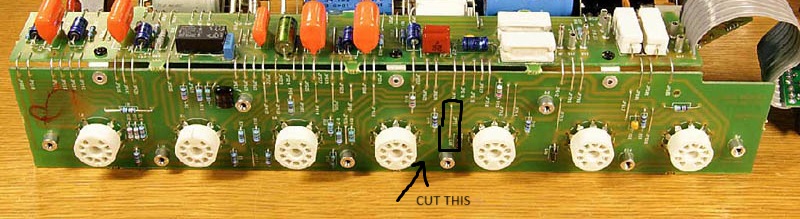
So how exactly do we accomplish adding these screen resistors in? Well we’re gonna have to remove the original 100ohm resistors and do some trace-cutting to properly feed each tube’s screen the correct resistance from the screen supply. Below I’ve attached the schematic for the Classic 30 which shows the arrangement of the screen resistors, and I’ve also attached a crude drawing of how we plan to alter this arrangement.
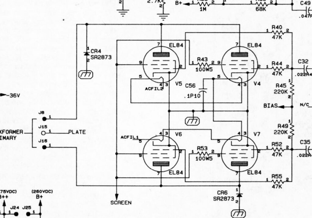
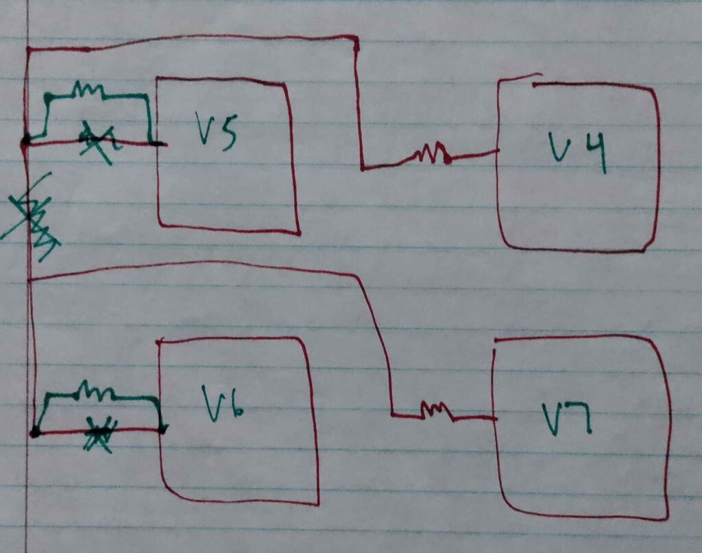
So as we can see we need to cut that trace connecting the screen of the V5 and V6 tubes together. Now the schematic alludes to another trace connecting each screen to the screen supply on V5 and V6, which would necessitate cutting those as well so it doesn’t short out our added resistor. However, in reality this doesn’t exist on the board so we don’t have to worry about that. Thankfully the service manual for the Classic 30 also gives us a clear scan of the board layout so we can trace out what points we need to make this happen (sidenote: if you’ve dabbled into old service manuals before you know how valuable a proper good quality scan of the board outline is; I swear 90% of the time any board outline scan from before the year 2000 is practically unreadable). So below I’ve attached a crude drawing of what I believe to be the best way to accomplish adding these two resistors to the corresponding screens of V5 and V6, I confirmed this board outline on the actual PCB using a multimeter as well. There are other ways of accomplishing this but in my opinion this is the least painful.
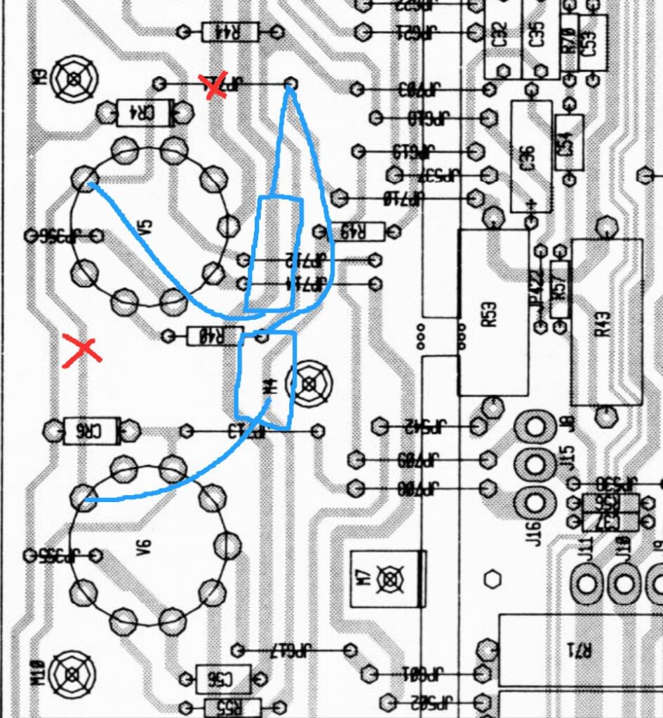
So as we can see, we need to cut that bottom trace shorting the screens of V5 and V6 and we also need to cut the connection that shorts the screen of V6 to the screen supply. We can also see that jumper that goes to the screen supply also hooks up with R53 and R43 which are the screen resistors for V4 and V7 which are cut off in this screenshot. So basically, we can choose between clipping that physical jumper and running the two leads of both of our added resistors to the node that leads to the screen supply, or alternatively we could cut the trace between that and the jumper that goes to the other board and run the resistors on that second jumper. Either way works, but I personally am for the former method. We can also additionally add some adhesive to these resistors later so they don’t move around too much, especially since these connections are gonna be made on the bottom of the board.
Additional Things to Look Out For:
Okay so those are the main things that we want to tackle when servicing this amp but there’s also some other bits of housekeeping we can do while we’re in here. I would recommend doing some of these additional procedures, especially since you really don’t want to open up this amp again if you can help it, but these are all optional.
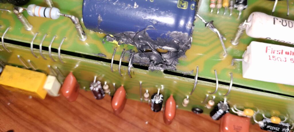
The Two Toasty Resistors:
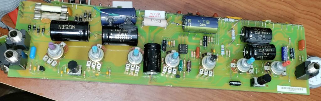
So once you open up the board you will probably notice this nice big burn mark on the board under these two 3ohm 5W resistors
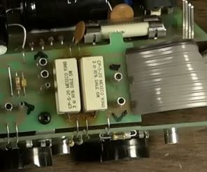
This shouldn’t be super alarming as this is an issue with pretty much every OG Classic 30. Basically these resistors are right on the bridge rectifier for the orange lower voltage transformer’s secondary (I’m calling it orange since that’s how they refer to it in the schematic). As a result, they get pretty hot and Peavey mounted these big cement wirewound resistors right on top of the board so overtime they start cooking the board resulting in this discoloration we see here. Honestly, you could probably leave this alone and the amp would be fine, but I don’t think its the safest thing in the world so I would recommend replacing them if you’re gonna be in here anyways. Any 3ohm 5W resistor will do and just like I described in the previous section, the rounded wirewound resistors may be preferable since they are smaller and wont get so close to the board like these ones. Regardless of what resistor you use as a replacement just make sure you keep them elevated off the board so this doesn’t happen again. I will warn you, as you will see later, this is easily one of the most annoying parts of the entire repair/servicing process for the amp, so if you want to skip this I don’t blame you.
Other things:
Other than these resistors you probably want to thoroughly check the board for corrosion, poor solder joints, and especially broken jumpers (you will see soon it is very easy to break these annoying little jumpers). I would actually recommend continuity testing every jumper before you put the board back inside the chassis. I would also recommend checking the speaker jack joints and reflowing the tube socket joints as well. Make sure you clean the pots and give the board a good scrub with some isopropyl alcohol, these boards have been out and about to various gigs over the past 30 years they deserve a good cleaning.
The Servicing Process
Disassembly:
Okay so I’m going to skip the disassembly process for the most part since honestly the blog page over at bustedgear.com will do a better job than I can describing how to open this thing up. I will add some grievances I had with this disassembly and some additional tips.
For one, the reverb connector is the most annoying part of this disassembly and will basically keep the chassis planted in the speaker cab until you unplug it from the board. Also the chassis is basically stuck there even once you unplug this connector since the grommet is too narrow to slide the connector out. Other than this, the disassembly process is mostly fine, and I think some of the complaints are mostly there because a lot of these older amps don’t require removing the board from the chassis, and as a result these extra steps are huge timewasters for amp techs. Moreover, you basically have to reassemble the chassis entirely to test the thing which means you really want to be sure everything is correct before you start testing this thing.
I’ll also add I managed to strip some corroded screws on the tube socket. Thankfully, a cheap screw extractor I bought managed to pull out the nasty stripped screw (using the #0 extractor bit and a 1/16″ drill bit). If you’re wondering what screws are good replacements, #4-40TPI screws worked for me, but since I could only find half inch long ones at my local Lowe’s, I had to add two washers to get it to the same length as the original screws. For those trying to get metric screws, unfortunately the thread pitch will be way too different to use common metric screws as replacements. I hate the American standard of screw measurement but there’s no other option i this case.
Once you remove the washers and pinch the board out of place you can finally begin your servicing.
Replacing the Capacitors:
So this is the part a lot of people dread, in my opinion because of a lack of good procedure. I would recommend doing this first before you make any other repairs.
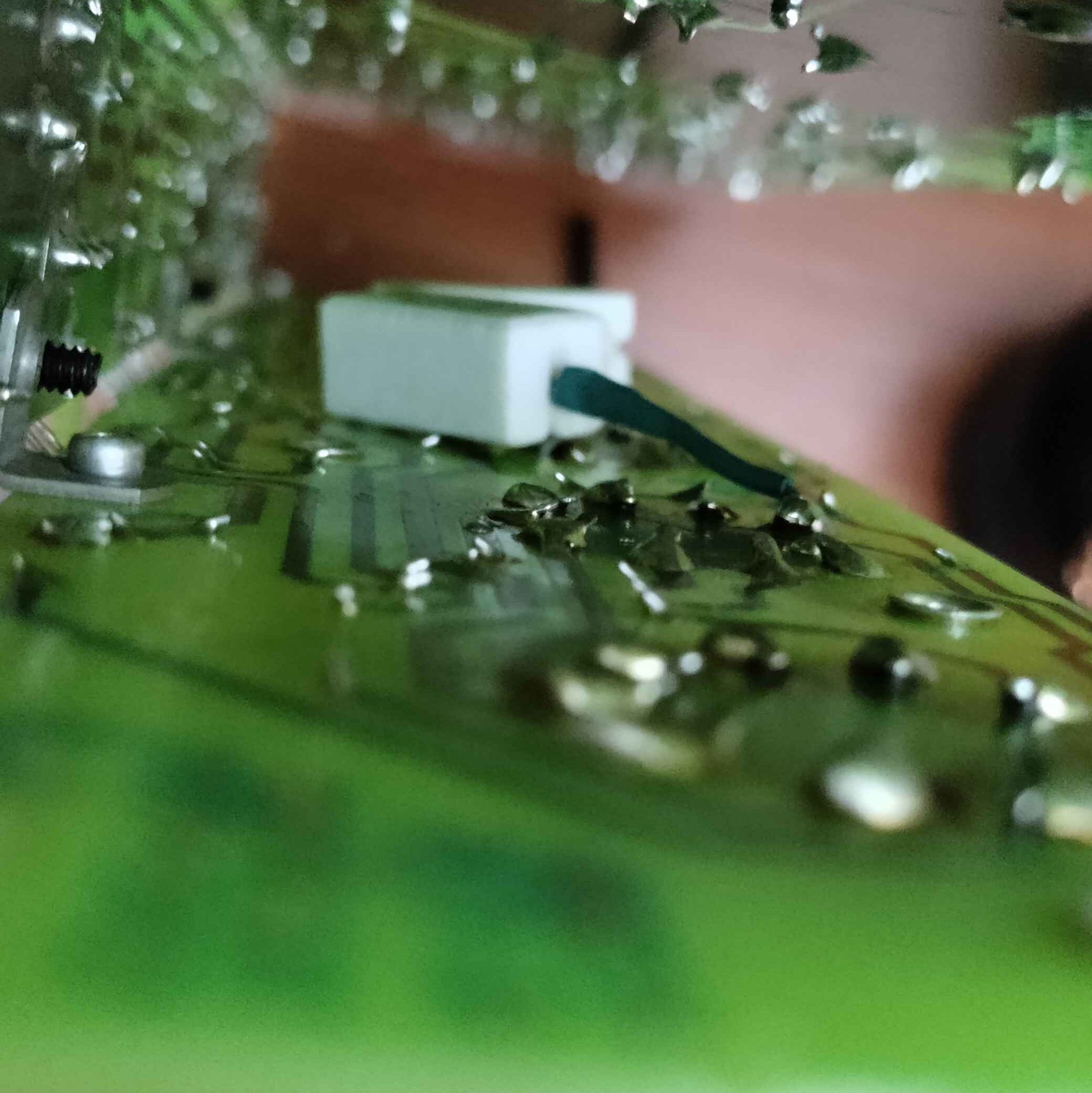
The Glue:
A lot of people have trouble getting this nasty thick adhesive off that bonds the capacitors to the board preventing them from vibrating and stressing the solder joints.
If you’ve worked with adhesive on electronics before, you’ll know the best way to get rid of this adhesive is using some 91% or 99% Isopropyl alcohol to soften it. I personally have mine in a spray bottle I got from dollar tree. Spray a generous amount on the area with the adhesive and the pry a spudger underneath the globs of glue. Make sure you’re holding the underside of the board with your free hand to prevent the pressure of your pry tool from stressing the metal jumpers. Rocking the caps back and forth will also easily allow you get under the softened glue and peel it off in big chunks. Some people also like to heat the glue to aid in this and yes this can help but I found it to be not really necessary if you follow the steps I laid out. This will work well for any cap on the board and will turn a 15 minute job into a 4 minute job.
After you get most of the adhesive off the cap you plan on replacing (I would recommend doing 1 or 2 at a time to avoid mistakes) you want to clip the leads of the capacitor off with a flush cutter as close as possible to the board. Once you’ve removed the capacitor you should take some time to clean the area with more isopropyl alcohol. I like to use a toothbrush on my first pass and then come back with a Q-tip to make sure the gunk is off the board.
Now that you’ve clipped the cap, you’re gonna turn over the board and desolder the little remaining piece of the lead that’s still soldered into the board. This is where I address the elephant in the room. To work on this board you are gonna have to stretch the U-shaped assembly just a little bit, but you want to be gentle and make sure not to disturb the jumpers too much. Only open it as much as you need to work on it, if you start to try opening this thing up flat you will end up breaking some of these fragile jumpers holding the assembly together.
To desolder the leads, its gonna be difficult to find the clearance to get a solder sucker or desoldering station in there. The best method I found was to heat the joint with the iron on the bottom side and pull the lead out with tweezers on the same side whilst the joint is molten. If you’ve left a long bit of the lead in when initially clipping them, then you might need to use something to press it down from the topside whilst heating the joint. This is because its relatively easy to accidentally push the lead up when trying to pull it out from the bottom if you’ve left too much excess on the top. This makes the process of grabbing enough of the lead to pull out a little more difficult, so this is the remedy I chose to use when I mistakenly didn’t clip enough of the capacitor lead off. Make sure you don’t use your bare hands to do this! You will burn yourself!! This is why I recommend clipping off as much as you can.
Once you’ve pulled the leads out you’ll realize this method will usually clear the hole without having to utilize a solder sucker or solder wick to clean up the joint enough to stick the new capacitor leads through. I would still highly recommend using solder wick to clean up the joint before inserting your new capacitors. After this the job is easy, just put the new caps in, bend the leads and solder the joints.
Making Your Radial Caps Work as Replacements for the Axial Originals:
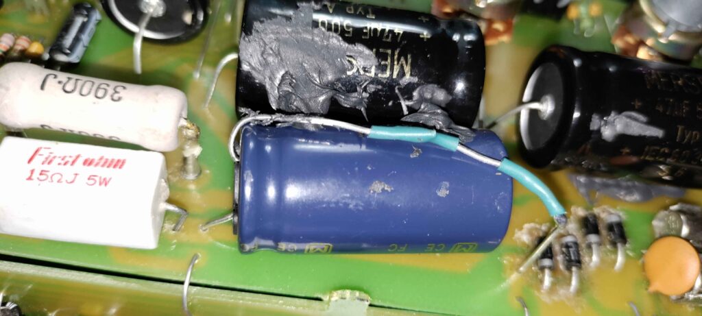
Now we’re gonna go back to something I referenced previously about using radial electrolytic caps as a replacement for the 2200uF 50V axial caps. The problem is if you try and insert them straight in they extrude far too much from the board. So we want these caps to basically be in the same form as the originals to avoid clearance issues inside the chassis and to keep everything nice and neat. To do this, We can put the cap on its side and solder one lead right to the pad where the original one is. The problem we now run into is that the other lead isn’t long enough to get to the other pad. So what I decided to do is solder a bit of the lead we just clipped off of the original cap to this lead. We can then bend it down to reach the pad so we can preserve the original orientation. I would recommend using some flux when attaching the leads together and, if you can, you should probably solder them before you solder the other lead into place. I put some heatshrink on the joint where I attached the two leads just to be safe. The result can be seen below. Pay close attention to proper polarity to avoid ruining your work.
Wait What’s That Black Stuff?:
So remember all the glue we removed? Well it does have a purpose, its there to make sure the caps don’t move around and weaken the solder joints over time due to this. You can absolutely skip putting on new adhesive, but I decided to be safe and put it back on. So this is Permatex UltraBlack RTV Sillicone. I would recommend using this specific silicon adhesive because it contains an oxime curing agent, which is not conductive and will not corrode over time. The only safe silicone adhesives you should consider for electronics stuff like this are ones with “neutral curing” which use either oxime or alkoxy sealants as opposed to acetoxy. DO NOT USE ACETOXY SILICONE ADHESIVE ON PCBs!!! A clue to look for when trying to pick the right adhesive is they will often label neutral curing adhesives as “sensor-safe” though I would double check the mandated safety sheet and look over the ingredients just to be sure. I’m putting this here because I have learned RTV Silicone adhesives are not all made equal, but people on forums will vaguely tell you to just get any RTV silicone adhesive and you’ll be fine.
I will be the first to admit my glue job here is not pretty, but it holds well enough and does the job despite being ugly. If my local Home Depot had a different color adhesive I promise it wouldn’t look as bad.
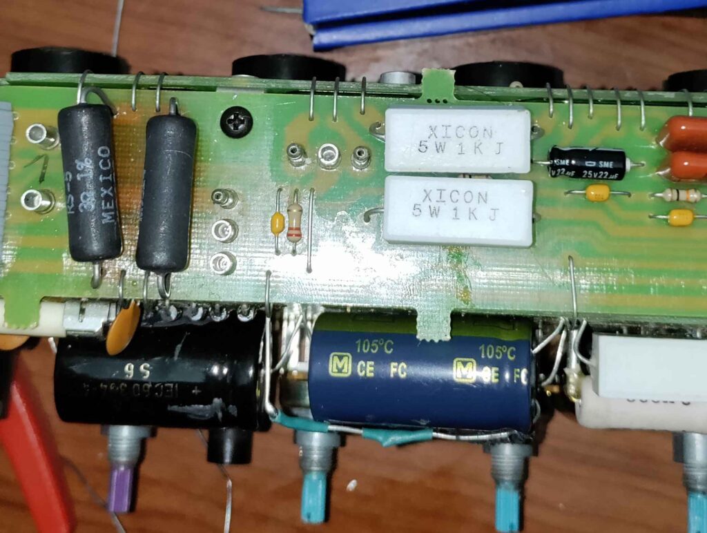
Replacing the Resistors:
So ideally we want to replace those two resistors cooking up the board and replace the two under-spec’d screen resistors as well. We aren’t going to tackle adding the two new screen resistors to V5 and V6 yet since that is better to do last to avoid clearance issues in this already tight board layout.
The most annoying part of this entire process will be removing those two problematic resistors R71 and R72. For some reason they soldered together with some of the aforementioned jumpers right on the edge of the board. This means its really easy for part of the lead to get stuck in between the boards when removing it the same way we did with the capacitors. If this happens to you, I would recommend trying the cut the lead on the bottom side shorter to stop it from clashing with the corners of the two boards. The rest is the same procedure as what we did with the capacitors: repeat this for all 4 resistors you need to replace.
Reflowing:
So just before we tackle the rest of the screen resistors, this is the perfect time to start reflowing joints on the board that may have become stressed over years of abuse. This would be the tube sockets, TS jacks, and the potentiometers. There’s nothing super tricky about this other than having to maneuver around the board layout (I’d recommend using something to prop up the side parallel to the one you’re working on). The only tip I have is to use flux and also use some desoldering wick. If the joint you’re reflowing is dragging solder up when you take your iron off of it even when you’ve been heating it for a good bit, you’re gonna want to probably wick up some of that old solder before adding more to the joint to solidify the connection. This isn’t necessary for every joint you reflow but if you encounter this phenomena then I would 100% recommend removing that old crusty solder first so you can ensure your new reworked joints are as solid as they can be. Also keep in mind some of these points are gonna require more heat than you’re used to, especially if they’re on a large ground plane.
Adding the New Screen Resistors:
So now we’ve come to the final hurdle: adding the new screen resistors to V5 and V6. So as we outlined in the previous section, we want to first cut the trace connecting pin 9 of V5 and V6 together. The best way to do this is to use either an X-acto knife or the tip of a box cutter if you don’t have one. Simply score a line on the trace between those two points until your multimeter doesn’t read any continuity between them anymore. I will warn you this trace is quite tough, I’ve cut my fair share of traces before and this was easily the most resilient even though I’m using better tools than I was previously accustomed to. Once you’ve cut the trace, I’d recommend cleaning it with some ISP and then putting some type of conformal coating on top of it to give it some protection as this part of the board has a lot of high voltage and high current nonsense going on. I used some cheap UV-curable solder mask on my board, once again I don’t think its a necessity but I would do it just to be safe.
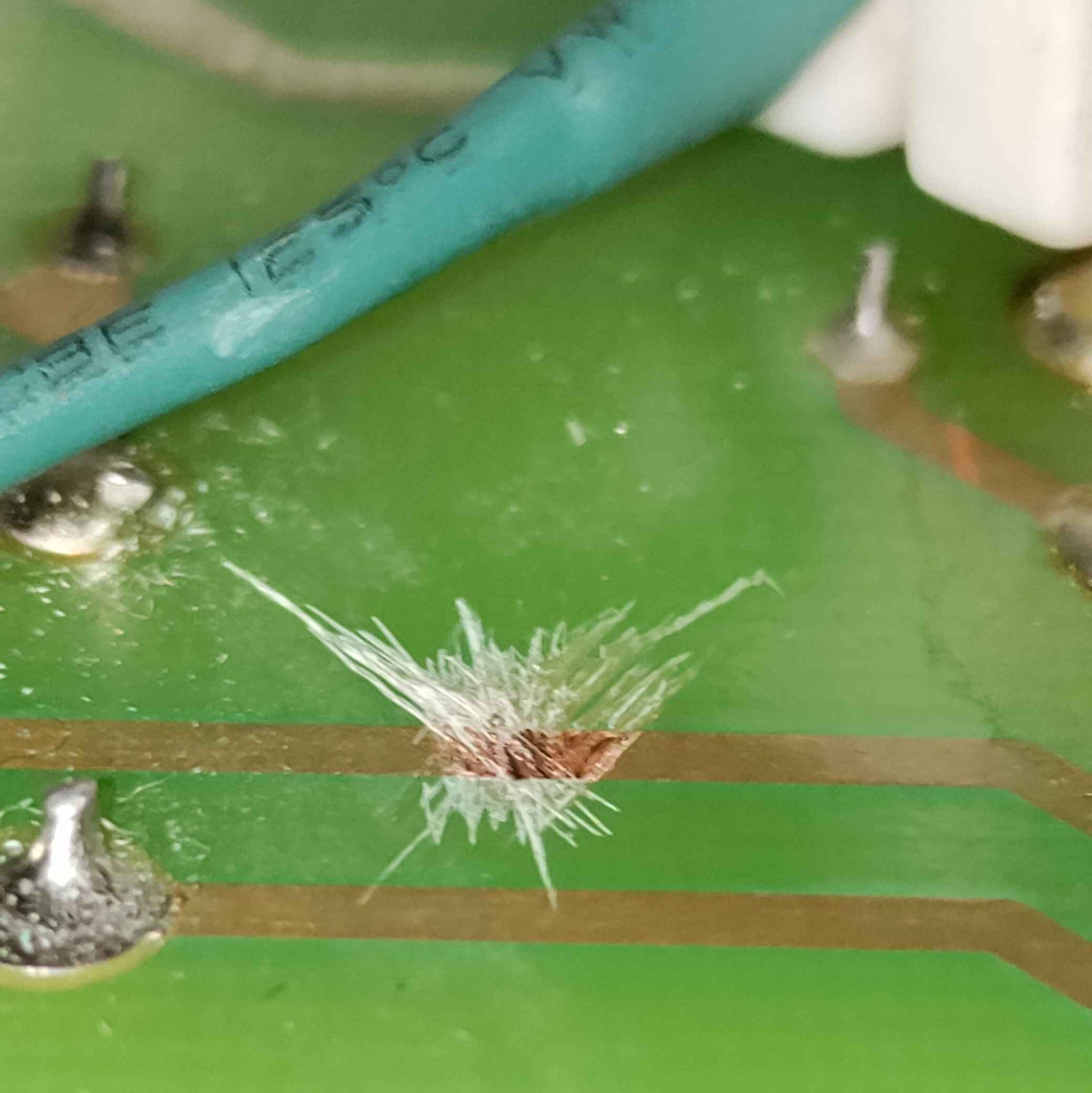
Once you cut this trace, you’re also gonna want to cut the jumper connecting pin 9 of V5 to the screen supply. To do this, just use some flush cutters and cut the jumper and remove enough excess so it doesn’t short anything out.
So now that we’ve done that, all thats left is to place our new screen resistors. I started with the one on V5 since it gives us enough room to do the next one without any issues. One thing I would recommend which I didn’t do would be to actually solder the legs of the two resistors together before soldering them to the board.. This will make the next steps much simpler since you don’t have to try connecting them while the board is still in this troublesome U-shape. Once you do this, you can solder the free leg of the first resistor to pin 9 of V5 and then solder the other leg on the other side of the jumper we just cut. I opted to attach some heatshrink to the leg going to the tube socket since its in such close proximity to the other pins.
Conclusions and Lessons Learned
Okay so I’m gonna be upfront and say this servicing did not fix my issue. That may seem like a pretty dissatisfying conclusion, but its a valuable lesson. See the issue the entire time was actually the simplest possible issue, which I thought i’d already done. It seems like one of the tube sockets was dirty and putting some contact cleaner on pins of the tube and using it to clean out one of the power tubes fixed my issues completely. I had cleaned it before but I guess I hadn’t done it properly. So after replacing all the tubes, caps, and some resistors for fun over the course of 2 days I found out almost two months later the issue is something I could’ve fixed without ever pulling the thing apart. Hindsight is 20/20 but honestly I didn’t think the caps were the issue in the first place, I was just trying to throw any solution I could at it. Hell I even tested a different speaker to make sure the stock speaker wasn’t faulty. I had to use an impedance matching transformer too because I didn’t own any 16ohm speakers.
By this point though, I had already bought the caps and resigned myself to servicing it with the tiny hope that there was actually something wrong with the amp and replacing the caps would fix this phantom issue. Well, by this point you can already guess what I found when I went through and replaced all the caps, reflowed the solder joints, and cleaned all the pots and tube sockets. Yeah, everything was perfectly fine. I tested every single capacitor and only a single one was less than perfect, a 2200uF cap that was just slightly below its rated capacitance and had a slightly higher ESR compared to the others (around 5ohms). This hardly could be considered a faulty cap, so basically every capacitor in this thing had a decent bit of life left in it. I don’t want to say I regret doing all this because at least I don’t have to do it in the future, and once again the amp is 30 years old it needs this treatment soon anyways.
This section was more of a warning to not get caught in the “it must be the caps” or “it must be this” mindset when it comes to electronics repair. I don’t have an oscilloscope and this amp is hard to test out of the chassis anyways so there was no way I could measure the amount of noise on each point of the circuit. The thing is, I should have explored other logical conclusions before just going “ah it must be the caps like it always is”. As many have said before, “recapping is not repair”. Repair requires history, a deep understanding of the issue, and most importantly testing. 90% of the time the stupidest possible issue is the main issue. Regardless, you should still service these things, they are old and many of them really do have leaky caps, crusty tube socket joints, and dirty pots. Just don’t go in expecting the caps are the cause of your issues unless you have undeniable proof through testing. I could’ve just lied to you and said “yeah after I serviced it the amp sounded brand new”, but I guess I have a humiliation fetish. If I had asked 4 different amp techs they probably would’ve told me it was the caps, and they wouldn’t be wrong for saying that.
Anecdotally, just to waste more of your precious time, I had an issue with a switching regulator that was giving me too much ripple voltage on the output. I thought it may have been the input cap since it was something I had to dig through my university’s lab to find, and I wasn’t entirely sure it was in working order. I asked 4 people and they all said “I doubt its the input cap”. “Its probably the output try putting another cap on the output” or “move the caps closer”. These are things I thought too, most of the time ripple on switching regulators is due to insufficient output capacitance or too much ESR on the output caps, and if its not that we can maybe say its the feedback or bootstrap caps because that whole network is a rabbit hole itself. Well I’m sure you can guess at this point it was the input cap, the least likely fault logically at least. I got bored and threw on an 0805 cap I found in the lab and what do you know it worked (the original was 1206). The point of this whole section was to hopefully hammer in the point, to both you, the reader, and myself, that you should explore every option even if it is “too simple” or something that doesn’t feel like it would be the main fault.
So Was it Easy?:
The last question I wanted to explore in this section is “was it really that hard? Well, maybe? Its probably more tedious and prone to error than your average tube amp from before the year 2000, but whether or not its as hard as the internet makes it out to be is another conversation. I have certainly worked on worse, I would much rather open this thing than a PS3. At the end of the day though, most people are gonna be paying someone to service this, and all the idiosyncrasies in the design of this thing will likely result in a larger quote.
I liken this amp to a car with a V6 in it. Replacing all your spark plugs and ignition coils in a V6 will cost you hundreds purely because the back 3 coils require you to remove the entire intake manifold, which is a huge huge pain in the ass. So your inline 4 engine you could easily replace the spark plugs yourself even as someone oblivious to car maintenance, but a V6 spark plug replacement will have you paying for over 3 hours of maintenance purely because of its annoying design. Okay I went on a little long with that comparison, maybe because I also wanted to vent about my car frustrations and how much money my shitty Nissan has cost me over the past year.
To get back on track, this amp is tedious to service, but more than doable for most people with some experience in electronics. If you’ve repaired more complicated modern consumer electronics than this thing is a peace of cake in comparison to that. If you’re just a vintage amp guy or a complete noobie than I would take caution and be in for a slightly frustrating and very tedious ride ahead of you. I hope this helps you wherever you are on that spectrum, and I still encourage anyone to actually give these amps a chance on the bench.